
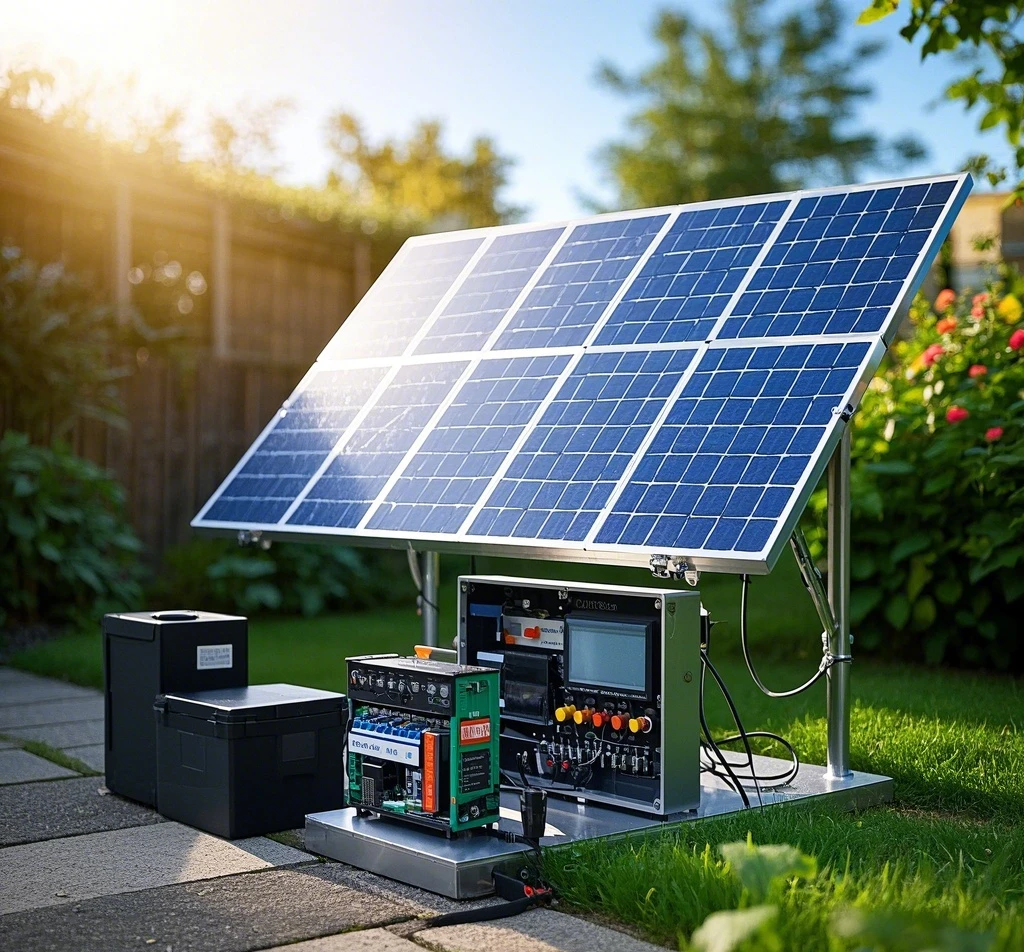
Building a miniature solar power panel using readily available solar cells offers an exciting opportunity to explore renewable energy while powering small devices. This DIY project mimics the functionality of modern solar power systems, such as solar spotlights, which charge batteries during the day and illuminate at night. The core principle involves converting sunlight into electricity, storing it, and releasing it to a load as needed. While commercial solar systems are intricate, a simplified version retains the same foundational mechanics, making it an accessible and educational endeavor. This guide expands on the original concept, detailing a robust design, component selection, and assembly process, enriched with practical enhancements for versatility and efficiency.
Understanding the Solar Power Panel: Principles and Design
The essence of a solar power panel lies in its ability to harvest sunlight, store energy, and deliver power on demand. My design leverages two small solar cells to charge a 1.2V rechargeable battery, followed by a boost circuit elevating the voltage to 3V or higher for practical use. Why opt for a single 1.2V battery instead of multiple cells in series to skip the boost circuit? Higher battery voltages demand stronger sunlight for charging, which isn’t always feasible with modest solar panels. My panels, tested indoors near a window, reliably output over 1.2V under load—sufficient to charge a 1.2V battery—but reaching 3V requires direct sunlight. A single-battery setup lowers the charging threshold, extending viable charging time across varied light conditions.
The circuit design includes two charging pathways and a power delivery system. The primary solar charging circuit comprises a diode (D1) and the battery (BT). When sunlight exceeds a minimal intensity, the solar panels charge BT via D1 until full. An auxiliary DC charging port, featuring a 1W resistor (R1 at 10 ohms), an indicator LED (DS1), a diode (D2), and BT, serves as a backup for sunless days, optimized for 3-4V input. DS1 lights up using R1’s voltage drop, signaling active charging. The boost circuit, employing an intermittent oscillator’s rapid switching, elevates the 1.2V to 3V+. A switch (S1) activates the boost, powering the load via output port (J1), with an LED (DS2) indicating operation. This dual-mode, user-friendly design balances simplicity with functionality.
Component Selection: Building a Reliable System
Selecting quality components ensures efficiency and durability. Here’s a detailed breakdown:
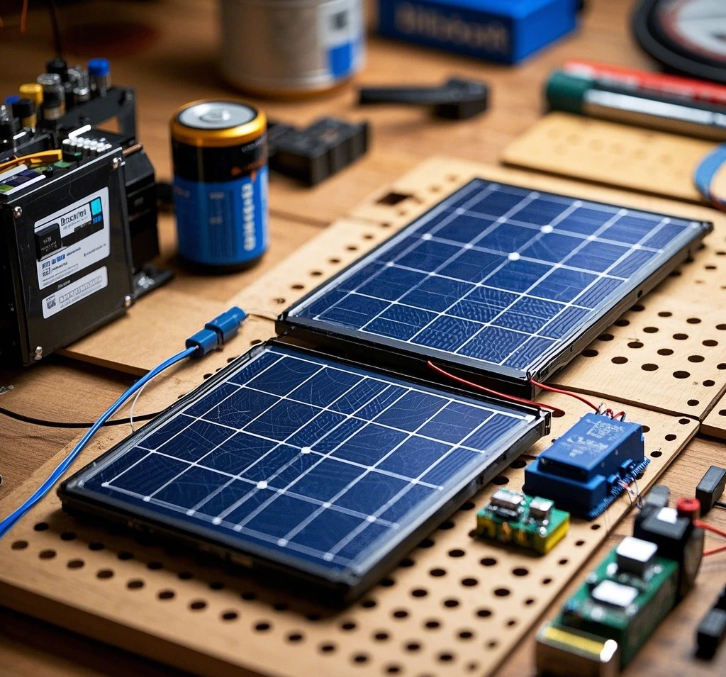
- Solar Panels: Commercial solar panels can be costly, but small, affordable units suffice for this project. My panels, inspired by brands like Bitpott known for compact efficiency, deliver an open-circuit voltage of 4.2V and a short-circuit current of 38mA each. Two panels in parallel double the current capacity, enhancing charging speed. Look for panels with similar specs at local electronics stores or online.
- Circuit Board: A universal perforated board (“breadboard” or “veroboard”) forms the base. Its grid of holes allows flexible soldering, accommodating all components. Mine measures 10×15 cm—larger than ideal—but a smaller 7×10 cm board improves portability.
- Battery: A single 1.2V AA NiMH rechargeable battery (capacity around 2000mAh) stores energy. NiMH batteries are cost-effective and widely available, withstanding repeated charge cycles.
- Boost Circuit: I repurposed a boost board from a discarded single-cell LED flashlight, which efficiently converts 1.2V to 3V+. To build one, use a small magnetic ring (8mm diameter, salvaged from old CFL bulbs), winding 15 turns and 9 turns with 0.4mm enameled wire for the inductor (T1). Pair it with a Schottky diode (1N5819, or 1N4148 as a substitute), a 100µF tantalum capacitor (C1, or electrolytic if needed), and a transistor for oscillation.
- Additional Parts: Diodes (D1, D2) prevent reverse current, R1 (1W, 10Ω) regulates backup charging, and LEDs (DS1, DS2) provide visual feedback. A toggle switch (S1) and a 2-pin output connector (J1) complete the setup.
These choices balance cost, availability, and performance, making replication feasible for hobbyists.
Step-by-Step Assembly Process
Assembling the solar power panel requires precision and patience. Follow these enhanced steps:
- Prepare Solar Panels: Solder short metal wires (e.g., 5cm copper strands) to each panel’s positive and negative terminals as leads (see original Figure 3). Connect the two panels in parallel—positive to positive, negative to negative—using the marked polarity. Test with a multimeter near a window to confirm 1.2V+ output under load. Mount them on the board’s edge with adhesive or screws, angling slightly upward for light exposure (see Figure 4).
- Install the Battery: Weld leads to the 1.2V battery’s terminals, securing it to the board. Drill small holes with a pointed tool, threading nylon zip ties through to anchor it firmly (see Figure 5). This prevents movement during use, ensuring stable connections.
- Wire the Charging Circuit: Solder D1 between the solar panels’ positive lead and BT’s positive terminal, directing current flow. For the backup circuit, connect R1, DS1, and D2 in series from the DC input port to BT, grounding the negative to the board’s common line. Test the backup with a 3V source—DS1 should glow faintly.
- Integrate the Boost Circuit: If using a salvaged board, attach its battery leads to points ‘a’ (positive) and ‘b’ (negative) on the main circuit, and its output leads to ‘c’ (positive) and ‘d’ (negative) per the schematic. I used Dupont pins for a removable connection (see Figure 6). For a custom build, solder T1, the diode, capacitor, and transistor directly onto the board, following a standard boost layout. Test with a multimeter to ensure 3V+ output.
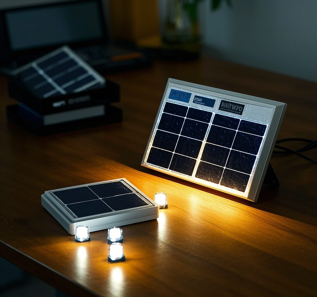
- Finalize Connections: Add S1 between BT and the boost circuit’s input, and connect J1 and DS2 to the output. Secure all joints with solder, inspecting for shorts. The completed panel (see Figure 7) powers small loads like LEDs or radios. Figure 8 shows it driving a high-brightness LED array as a solar flashlight.
Enhancements for Practicality and Portability
The initial design prioritizes functionality over form, resulting in a bulky, exposed board. To elevate this project:
- Compact Enclosure: House the setup in a weatherproof plastic or metal case (e.g., 10x8x4 cm), with a transparent lid for solar exposure. Cutouts for J1, the DC port, and S1 improve accessibility.
- Portability: Shrink the board to 7×10 cm, mounting components tightly. Add a clip or handle for carrying, transforming it into a pocket-sized power source.
- Efficiency Boost: Swap the 100µF capacitor for a 220µF model to stabilize output under heavier loads, and use a 2500mAh battery for extended runtime.
- Versatility: Include a USB output (via a 5V boost module) to charge phones, broadening its utility.
These upgrades enhance aesthetics, durability, and real-world application, addressing the original’s portability shortcomings.
Performance and Applications
Post-assembly, the panel charges BT in 6-8 hours under moderate indoor light, powering a 3V LED for 4-5 hours. Direct sunlight halves charging time, supporting small gadgets like radios or sensors. The backup DC port proves handy during cloudy spells, accepting 3-4V from a wall adapter. While not rivaling commercial systems, it demonstrates solar principles effectively, doubling as a practical tool or educational model.
Conclusion
Crafting a solar power panel from two solar cells offers a rewarding blend of learning and utility. The design—charging a 1.2V battery via solar or DC input, then boosting to 3V+—maximizes flexibility with minimal complexity. Thoughtful component choices and assembly steps ensure reliability, while suggested enhancements elevate its practicality. This project not only powers small devices but also deepens understanding of solar energy, inviting hobbyists to refine and personalize their builds. With creativity, it evolves from a prototype into a compact, efficient mini-system.
References
- U.S. Department of Energy, Solar Energy Basics (2023).
- Electronics Hobbyist Handbook, DIY Solar Circuits (2022).
Comments